The short pulse, very high current capabilities
of the induction linear accelerator make it a logical candidate
for certain applications to diagnosing physical properties. Two
examples are fast high density explosive experiments and material
science using neutron scattering. Flash x-rays are needed for
imaging high density metal compression experiments. The short
(50-75ns) pulse-burst capabilities of the induction linac are
well suited to this. Because high x-rays doses are necessary
to image the experiment and characterize density variations the
multi-kiloampere capabilities of induction machines are attractive.
Short neutron pulses from proton induced spallation can provide
excellent energy and time resolution in material studies using
neutron scattering. The induction linac simplifies spallation
sources by transporting and accelerating the total beam current
necessary (amperes of H+) in a single beam with no
storage. Concepts for both applications are discussed with emphasis
on technical risks and costs.
Induction linear accelerators have properties
that make them valuable in physics diagnostics applications.
These properties are the ability to accelerate very intense beams
and the ability to generate discrete short pulses1. The two applications
discussed here are the use of proton beams to generate spallation
neutrons for material science, chemistry, and biology and the
use of short high current electron pulses for fast time resolved
radiography of dense rapidly moving objects. Induction linacs
can accelerate any beam current that the transport system is capable
of handling provided that the pulser that drives the accelerator
cells can supply the required current. This is because induction
accelerators do not suffer from the cavity loading effects that
occur in RF machines. However, fast rep rate pulse power systems
have design problems of their own, such as switch and component
lifetime, and cost.
In the application of such machines
to a spallation neutron source, the main advantage is that one
can accelerate the entire beam current required on the spallation
target in a single pass thus eliminating the need for a storage
ring. Not using a ring eliminates the need for H-
ion sources which are a more complex and a lower current density
technology than H+ sources.
The absence of a ring also avoids the problems associated with
stripper foils and excited neutrals. By extracting the required
short pulse directly in the injector one avoids the beam chopping
problems of RF machines. Finally, since the physics limit placed
on the beam emittance in an induction machine comes from the final
focus conditions, the ion temperature of the source is not a limiting
factor. The very low emittance required for injection into a
ring is small compared to the emittance limit imposed
by final focusing in this application.
Radiography of fast moving dense objects
needs multiple pulses separated slightly in time and possibly
simultaneously from more than one direction to obtain 3D imaging
of the object. Such a project is underway at Los Alamos National
Laboratory called DARHT2 (Dual Axis Radiographic Hydro-Dynamic
Test facility). The physics requirements for this application
are quite severe: beam current of 4-6KA, beam energy up to 20MeV,
focal spot < 1mm, 4 pulse burst with 50-70ns pulse length
and 250ns pulse separation. Induction linac cells designed for
long pulse applications may be useful for this radiography application.
The first point is bunch dynamics in the machine. The simplest approach is to accelerate a bunch as a rigid body relying on acceleration to provide both current amplification and pulse shortening. One can also vary bunch lengths by varying the velocity along the bunch as a means to reduce the length of the machine. Designing for short length can reduce costs, but the limits on acceleration gradient may prevent this. Consider accelerating the head of the bunch according to a Z2 schedule, where Z is the distance along the machine, and accelerating the tail on a linear schedule. Now assume that the output beam has an energy of 1.25 GeV, a current of 57.5A, a pulse width of 580 ns, and a rep rate of 60 Hz. These conditions correspond to a steady state output power of 2.5 MW, reflecting the initial goal of the NSNS (National Spallation Neutron Source) design team for a machine between l and 5MW average power. Also assume a 2MeV proton injector generating 8µs, 4.2 A pulses, parameters achievable with technology developed in the LBNL Heavy Ion Fusion Accelerator Research3 program. The injection parameters come from imposing the condition that geometric length of the bunch is the same during its entry into the accelerator as during its exit. Inside the accelerator the bunch expands longitudinally before recompressing to its original length. Solving the relativistic equations of motion for the head and the tail with the entry and exit conditions listed above, yields a machine length of 1761m plus the length of the injector which might be 15m. There are two problems with this approach. First, the linear charge density in the bunch is 0.213µcoul/m which is very low in terms of the transport limits that can be achieved in quadruple or solenoid magnetic fields. More importantly, the peak accelerating gradient reaches 1.42MeV/m for the head and the linear gradient for the tail is 0.71MeV/m. Figures commonly used for the technologically achievable gradient range from 1Mev/m and to a more realistic 0.5MeV/m.
Assume a more practical acceleration
gradient of 0.5 MeV/m and use a higher linear charge density that
makes more efficient use of transport capabilities. Making the
beam diameter small also reduces the mass of core material for
a given number of volt-seconds (pulse voltage times pulse duration)
and a given core length. In this case the beam bunch enters the
accelerator completely before the acceleration cells are turned
on. The entire bunch is then accelerated at the same rate and
therefore the bunch length remains constant through the machine.
E.P. Lee4 has developed an envelope equation model to calculate
the space charge transport limit for a given quadrupole focusing
channel. This analytical model incorporates consistent expansions
in KL2 where K is the quadrupole strength and L is the lattice
half period and gives errors less than 2%. From the equations
one can derive an expression for the quadrupole magnetic field
gradient in terms of the linear space charge density , ![]() ,
the beam maximum radius, a, the normalized emittance,
,
the beam maximum radius, a, the normalized emittance, ![]() N,
and the relativistic constants,
N,
and the relativistic constants, ![]() and
and ![]() :
:
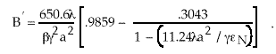 . (1)
. (1)
Using this expression one finds that
it is feasible to triple the linear charge density to 0.639µcoul/m.
The injection bunch length is reduced from 157m to 52.3m. The
resulting higher injector current is not a problem. One can transport
this bunch within a maximum radius of 1.5cm in a quad system with
pole tip field .77T and bore radius of 4cm. The effects of quad
length and the bore size on aberrations present no problem. The
resulting accelerator is 2548m long plus the 2MeV injector and
produces 200ns pulses at 60Hz with an average power of 2.5MW.
The accelerating cells are 250KV each, using Metglas as the core
material; there are 4992 of them in the main accelerator and
105 in the bunch entry section just after the injector.
This design was costed using scaling
rules and experience from the Heavy Ion Fusion and RTA programs.
The result was a total accelerator system cost of $542.7M including
all design, assembly, and commissioning labor and overhead. A
permanent magnet qudrupole transport system was assumed to minimize
core inner radius relative to room temperature or superconducting
sytems. Dropping the exit energy from 1.25GeV to 1GeV, eliminates
500m of accelerator length at the cost of dropping to 2MW average
power but with a financial saving of $85.1M. The exit pulse length
remains essentially the same. This cost must be viewed with considerable
caution. The design was a first cut point design. Second, "rule
of thumb" scaling laws based on various peoples' experience
were used and the bias was toward conservatism. A more detailed
design is needed to achieve reliable costs with computerized cost
models. The transport system represents $87M but is based on
an unoptimized constant period configuration. Substantial saving
could result from better design. The cooling budget is $78.4M
and probably could be reduced by better design.
In addition to the cost uncertainties
there is technical risk. The issue of getting the 12.5A proton
current out of the ion source with suitably low emittance for
target focussing is not a problem. However fast pulse extraction
preserving good beam optics from the gas source is. Recent work
at LBNL on source beam chopping may provide the solution to this
problem but experimental work is needed. Another risk is the
lifetime and reliability of the pulse power components. Operation
at 60Hz for 24 hrs/day and 80% up time implies 1.5X10⁹ pulses
per year. Life tests at LBNL using FET switches have reached
2.5X10⁷ pulses at 72Hz on a nickel-iron core and 2X10⁸ pulses
at 100Hz on Metglas both with convective air cooling. The systems
were still operational at conclusion. Further experimental work
especially on cheaper thyratron switches is needed to reduce risk
and to define cooling requirements better. The beam clearances
used were based on theoretical models used in the Heavy Ion Fusion
program in which beam halo was not a consideration. This problem
needs further study to better define the clearance requirements
which in turn affect the cost of the magnets and cores. Finally,
at short pulse lengths(< 0.5 µs), the power loss
in Metglas cores grows quickly. Consideration should be given
to ferrite materials which cost more but which would reduce cooling
requirements and operational costs.
Long pulse induction linac technology
under development for heavy ion inertial fusion may be suitable
for the radiography application. A gated cathode of some type,
either electronically or laser switched, could supply a train
of pulses to the accelerator. The pulse duration and separation
would be governed by the cathode system while the voltage that
accelerates the beam would be on throughout the burst. The two
most important problems in the linac design are the accelerator
cell voltage flatness and the transverse mode impedance of the
cell. Other physics issues include especially the interaction
between the intense beam and the bremstrahlung target, corkscrew
motion of the focal spot due to beam energy variations, and emittance
growth.
An induction linac cell is normally
designed to operate with a pulser that is matched to a specific
beam load. If the beam is not present while the voltage is on,
an overvoltage condition on the acceleration gap and the cell
insulator will be created. One way to deal with this problem
is the use of a compensation resistor in the pulser circuit.
The pulser then sees the core magnetization current, the beam
current, the compensation resistor current, and the gap capacitance
all in parallel. If one dominates the loading with the compensation
resistor the system efficiency will be low but in a testing application
like this, efficiency is not important. In this concept one is
deliberately creating a beam on-beam off situation and therefore
much attention needs to be devoted to this problem. Not only
is it a high voltage design problem but also a beam chromaticity
issue. If the accelerating voltage is not at its nominal value
when a bunch arrives, the change in beam energy will contribute
to transverse motion of the focal spot which reduces the geometric
resolution of the radiography system.
Another approach is driving a large
core, containing sufficient volt-seconds to accommodate the number
of beam pulses required, with separate pulsers that are electrically
isolated from each other. There are two ways of isolating the
pulsers. One is diodes and the other is to use a switch capable
of holding off the acceleration gap voltage in the back direction.
In the case of diodes the problem is to provide enough back voltage
isolation to withstand the full acceleration gap voltage of possibly
250KV. Also the diodes must be capable of handling the full discharge
power in the forward direction. It is probably easier to use
high voltage switches such as thyratrons or spark gaps. This
approach has the disadvantage of requiring multiple pulsers which
represent extra cost, but the advantages are avoiding the load
matching problem and allowing the use of less Metglas by not maintaining
voltage during periods when the beam is absent. A third possibility
is the use of branch magnetics5 to drive the core without resetting
between pulses.
The beam breakup (BBU) instability in
linear accelerators is driven by coupling between longitudinal
beam motion and the excitation of transverse modes in the acceleration
cavity6. The BBU parameters for the existing DARHT first axis
cells have been thoroughly studied. Changing to a new cell design
will require detailed computer simulation to understand the precise
properties of the new cavities. A code such as AMOS7 will have
to be modified to include the properties of Metglas for the calculation
of the transverse impedances of the new cavities.
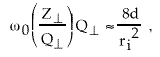
In the modeling of BBU the parameter6
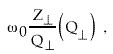 , (2)
, (2)
where ![]() is the
transverse mode impedance of the dominant transverse mode and
is the
transverse mode impedance of the dominant transverse mode and
![]() has the value for this mode, is an important
quantity in the growth rate for the instability. It is therefore
important to consider how this factor will change if one makes
simple changes in the existing cavity by changing the feromagnetic
material. Consider a simple cylindrical cavity in which one first
has ferrite suitable for 70ns pulses and then replaces it with
Metglas for 1µs constant voltage pulses. The total mass
and therefore the cost of the core depends on the inside radius,
the core length and the required cross section. If a length of
the cavity has been chosen by system considerations the, core
cross section is determined by ÆB(r0
-ri
)d = Vp
has the value for this mode, is an important
quantity in the growth rate for the instability. It is therefore
important to consider how this factor will change if one makes
simple changes in the existing cavity by changing the feromagnetic
material. Consider a simple cylindrical cavity in which one first
has ferrite suitable for 70ns pulses and then replaces it with
Metglas for 1µs constant voltage pulses. The total mass
and therefore the cost of the core depends on the inside radius,
the core length and the required cross section. If a length of
the cavity has been chosen by system considerations the, core
cross section is determined by ÆB(r0
-ri
)d = Vp![]() where Vp is the gap voltage,
where Vp is the gap voltage, ![]() is the effective pulse length, and ÆB is the total flux
swing before saturation allowed by the ferromagnetic material.
The question is what happens to the quantity
is the effective pulse length, and ÆB is the total flux
swing before saturation allowed by the ferromagnetic material.
The question is what happens to the quantity ![]() while the outside radius r0
is changed to accommodate the
change in material and the change in
while the outside radius r0
is changed to accommodate the
change in material and the change in ![]() while keeping d and ri fixed.
Therefore r0
= (Vp
while keeping d and ri fixed.
Therefore r0
= (Vp![]() /ÆBd)+ri .
/ÆBd)+ri .
A single pill box model8 of an induction
cell cavity has a transverse mode impedance estimated by
![]() =
= 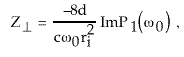 , (3)
, (3)
where ![]() is a
function determined by d, ri, and the ratio of assumed wall impedance
at the outside radius r0
to the impedance of free space. If one only increases or decreases
the cavity radius then
is a
function determined by d, ri, and the ratio of assumed wall impedance
at the outside radius r0
to the impedance of free space. If one only increases or decreases
the cavity radius then
 , (4)
, (4)
For a given current, machine length,
number of cells, beam noise spectrum, acceleration gap, and pipe
radius the BBU growth rate should not change. This is because
it is not the cavity in which the feromagnetic material for the
cell is contained that determines the ![]() of interest but rather the cavity that contains the acceleration
gap. This gap will probably not have a simple cylindrical shape
and transverse mode damping structures will be included in the
cavity.
of interest but rather the cavity that contains the acceleration
gap. This gap will probably not have a simple cylindrical shape
and transverse mode damping structures will be included in the
cavity.
The resonant frequency of a radial cavity
transverse mode is
 where
where ![]() , (5)
, (5)
is a constant dependent on the mode
number. If the change in radius causes the resonance of the relevant
mode to coincide with a portion of the beam noise spectrum that
is relatively high, the BBU growth will be more severe.
This work was supported by the U.S.
Department of Energy under Contract No. DEAC03-76SF00098.
[1] Principles of Charged Particle Acceleration,
Stanley Humphries Jr., John Wiley & Sons, 1986, ch. 10.
[2] M. Burns et al., Proc. 9th Int.
Conf on High-Power Particle Beams, Wash. DC, May 25-29, 1992,
p. 283.
[3] S. Yu et al., Proc 1995 Particle
Accel Conf and Intl. Conf on High Energy Accelerators, May 1-5,
1995, Dallas, Texas, p. 1178.
[4] E.P. Lee, Particle Accelerators, Vol. 52, 1996, p. 115
-132.
[5] H.C. Kirbie, et al., Proc. 1992
Linear Accelerator Conf. Ottowa, Canada, Aug 24-28, 1992, p.
595.
[6] G. J. Caporaso and A.G. Cole, Proc.
1990 Linear Accelerator Conf., Albuqerque, N.M., Sept. 10-14,
1990, p. 281.
[7] J.T. DeFord, et al., Proc. Conf on Computer Codes and Linear Accel Community, Los Alamos, N.M.,
Jan 25, 1990, p. 265.
[8] R. J. Briggs et al., Particle Accelerators, 18, 1985,
p 41.