The AllPix Simulation Framework
- Getting Started with
AllPix : Installation - Development in the AllPix Framework
- Working with the AllPix Framework
- Pixel detector geometry description
- Appliances and Test Structures
- Writing a Macro to drive your simulation
- Analysis of your Simulation results

Getting Started with AllPix : Installation
Latest Version
Allpix is migrating to github and a new repository has been created there to hold the future versions of Allpix. The current version is compatible with ROOT6 and GEANT4.10 To install the latest version ofPrevious Releases
Previous iterations of- Dependencies
- Download compile and run allpix with standalone geant4 installation
- Installation on lxplus
- Known Issues
Dependencies
The tricky dependency is OpenInventor (Optional). There is a number of ways in which you can install OpenInventor in your system. One (the most portable) is through the Coin3Dhg clone -r 11361 https://bitbucket.org/Coin3D/coinDownload and compile Coin and SoXt. ATTENTION soxt-config and coin-config programs should be in your path after installation. Basically libCoin replaces libInventor and libSoXt replaces libInventorXt. Later on, at running time, you have to produce the proper symbolic links in your system
libInventor.so --> llibCoin.so
libInventorXt.so --> libSoXt.so
The command to create that symbolic link (sudo might be needed depending where you install is located) is :
ln -s SOURCE TARGETThe recommended version is geant4.10.00.p02 or higher. You'll find here he cmake set of parameters which will produce a built of geant4 which fully supports allpix. For installation details visit Geant4 home page
cmake -DCMAKE_INSTALL_PREFIX=/home/idarraga/hep/geant4.10.00.p02-install -DGEANT4_INSTALL_DATA=ON -DGEANT4_USE_GDML=ON -DCMAKE_BUILD_TYPE=Debug -DGEANT4_USE_OPENGL_X11=ON -DGEANT4_USE_XM=ON -DGEANT4_USE_INVENTOR=ON -DGEANT4_USE_QT=ON -DGEANT4_BUILD_MULTITHREADED=ON -DGEANT4_USE_GDML=ON /home/idarraga/hep/geant4.10.00.p02if everything goes smooth with cmake, now compile geant4 (you probably want to use many cores with -jN flag, where N is the number of cores)
makeIf you are compiling Makefile based projects, which is the case with allpix, you need to source this first (replace version with your current geant4 version)
source YOURPATH/geant4.9.5-install/share/Geant4-9.5.0/geant4make/geant4make.sh
Download compile and run allpix with standalone geant4 installation
Allpix code is available in the svn at CERN :svn co http://svn.cern.ch/guest/allpix/tags/AllPix_v1.0before compiling don't forget to source your Geant4 setup :
source YOURPATH/geant4.9.5-install/share/Geant4-9.5.0/geant4make/geant4make.shNow compile :
makeIf you are running the EUDET Telescope you need to setup the following env variable before "make" :
export EUTELESCOPE=1Run with visualization (Open Inventor) :
allpix macros/oneDetector_Inventor_vis.in
Installation on lxplus
A Standard GEANT4 (4.9.6.2) installation with SoXt and Coin3D support has been compiled and made available to lxplus (SLC6) users. To use this configuration , first check out the latest release of the AllPix Framework (currently 1.0)svn co http://svn.cern.ch/guest/allpix/tags/AllPix_v1.0In the downloaded folder, a bash script has been prepared to setup the GEANT4 and ROOT dependencies needed by allpix. The script (setup_allpix.sh) must be edited to provide geant4 with a folder to write down the temporary files and executables. Create a folder in your home or work directory (for example ~/Geant4_workdir). Edit the setup_allpix.sh file to point geant4 to this directory using the $G4WORKDIR environnement variable :
export G4WORKDIR=~/Geant4_workdirOnce this modification made, source the script and compile AllPix :
source setup_allpix.sh
make clean
make
Known issues:
[reported by I.Rubinskiy 21-03-2013] Ubuntu 12.04 64bit. Allpix fails to build the allpix executable complaining for missing xerces methods (as undefined). Solution 1: regress the compiler version to g++-4.4: CXX = g++-4.4 (in the Makefile) Solution 2: add more packages / the following recommendation was found at http://www.linuxquestions.org/questions/programming-9/undefined-reference-problem-819467/apt-get install libxerces-c2-dev libssl-dev libboost-dev swig[reported by J. Idarraga 18-06-2014] If prebuilding with cmake. For unresolved dependencies use the VERBOSE mode when compiling For Geant >= 4.10
$ make VERBOSE=1For GEant <= 4.9
$ export CPPVERBOSE=1
$ make
If anything missing you can append the libraries in the CMakeLists.txt file by using the command (for instance for missing libXt --> -lXt)
target_link_libraries (allpix Xt)And then cmake and make.
Development in the AllPix Framework
Users developing new digitizers and adding modifications to the AllPix framework are strongly recommended to use our SVN versioning system to keep trace of their modifications and allow for other users to benefit from the improvements added to the code. To gain authorization to commit code to the AllPix SVN, please email the current developer list to be added to the current developers e-group (allpix-dev@cernNOSPAMPLEASE.ch). To checkout a version for development, please use the secured version of the SVN repository :svn checkout https://svn.cern.ch/reps/allpix/tags/AllPix_v1.0or
svn checkout svn+ssh://svn.cern.ch/reps/allpix/tags/AllPix_v1.0The second step is to create your own branch of the development code :
svn copy svn+ssh://svn.cern.ch/reps/allpix/tags/AllPix_v1.0 svn+ssh://svn.cern.ch/reps/allpix/branch/NAME_OF_BRANCH -m "Creating a branch of project named NAME_OF_BRANCH"Finally switch you current checkout to the newly created branch, from the checked-out folder containing AllPix :
svn switch svn+ssh://svn.cern.ch/reps/allpix/branch/NAME_OF_BRANCHYou can then develop your code and commit it to your branch to keep track of your development. When creating a new release, AllPix developers will then be able to merge your improvement into the released version.
Allpix Digitizers
Allpix comes with a set of some useful digitizers to emulate the behavior of well-known pixel detector front-end like medipix. Click on the name of the digitizer for a description of its functionalities (Work In Progress)- AllpixTimepixDigitizer : This digitizer can be used to simulate Timepix familly chips.
- AllpixMCTruthDigitizer : This simple digitizer return only the hits energy for each pixel of the matrix. This is useful for debugging and developing new geometries or extracting dE/dX values.
- AllPixMimosa26Digitizer : This digitizer is use to simulate the Mimosa26 monolithic detectors, this digitizer has been calibrated with Test Beam data and should be used for the simulation of the EUDET telescope tracking planes
source newdigitizer.shA new class will then be created with the name AllPixYOUDIGNAMEDigitizer will be created and the corresponding source code will be created in the src and include folder of AllPix. This is then the user's responsibility to develop a digitizer for his purposes. A few digitizer covering most common user cases are also provided (see above).
Bug tracking
A JIRA bug tracker has been deployed to keep track of current issues affecting the AllPix Framework. To submit a bug/Feature request, please visit the AllPix JIRA page at https://its.cern.ch/jira/browse/ALLPIXWorking with the AllPix Framework
AllPix is a Geant4-based simulation dedicated to solid state detector technology featuring pixel and strip detectors is presented. The program allows the user to create a particular experimental setup with an arbitrary number of detectors in any desired configuration. Additional complex structures can be easily included thanks to Geant4 services. Different digitization strategies are available. The program also serves as a Digitizer development work-bench.Pixel detector geometry description
From the user stand point the simulation is driven from a regular Geant4 macro using standard GEANT4 macro commands where additional custom AllPix commands are available. The user may place as many detectors with as many geometries as needed. If the detectors overlap in space, AllPix will launch a warning at run time. The first step to create an AllPix simulation is to add a entry in the AllPix Pixel Detector database for the detector geometry you need to simulate. The Pixel Detector database is located in the models folder and is a standard xml file named pixeldetector.xml. Each entries in the Pixel Detector database should be structured as follow :<!-- Timepix --> <pixeldet id=Â800,801Â> # Unique identification number for the described device in the simulation, a unique id is needed for each instantiated devices <digitizer>Timepix</digitizer> # Digitizer ID, digitizer to be used for this device # Pixel matrix dimensions, pixel sizes are given in Half-Length ex: 55um pixel pitch -> pixsize_x = 27.5, # pixsize_z should be set at the same half-thickness ass the sensor <npix x>256</npix x>\n <npix y>256</npix y>\n <npix z>0</npix z>\n <pixsize x units=ÂumÂ>27.5.</pixsize x> <pixsize y units=ÂumÂ>27.5.</pixsize y> <pixsize z units=ÂumÂ>150.</pixsize z> # Sensor dimension, should be coherent with matrix dimensions, gr_excess define the size of the Guard Rings (Inactive Volumes) # around the active Matrix, sensor_pos describe the position of the sensor with regard to the PCB volume center (X,Y) <sensor hx units=ÂumÂ>7040</sensor hx> <sensor hy units=ÂumÂ>7040</sensor hy> <sensor hz units=ÂumÂ>150.0</sensor hz> <sensor gr excess htop units=ÂumÂ>100.0</sensor gr excess htop> <sensor gr excess hbottom units=ÂumÂ>100.0</sensor gr excess hbottom> <sensor gr excess hright units=ÂumÂ>100.0</sensor gr excess hright> <sensor gr excess hleft units=ÂumÂ>100.0</sensor gr excess hleft> <sensor posx units=ÂmmÂ>0</sensor posx> <sensor posy units=ÂumÂ>14080</sensor posy> <sensor posz units=ÂmmÂ>0.</sensor posz> # chip Geometry : Define the size of the Chip side of a Pixel detector # chip_offset describe the offset between the chip and sensor volume sensors, for example, if bonding pads are present <chip hx units=ÂumÂ>7040</chip hx> <chip hy units=ÂumÂ>7040</chip hy> <chip hz units=ÂumÂ>75.0</chip hz> <chip_offsetx units="um">0.</chip_offsetx> <chip_offsety units="um">-1020.</chip_offsety> <chip_offsetz units="um">0.</chip_offsetz> # Bump-Bonding geometry : Bump bonds are modeled as the union of a # Cylinder(height ->bump_height, radius ->(bump_radius - bump_dr) ) and a Sphere(r->bump_radius). Offset is relative to the center of the pixel <bump_radius units="um">9.0</bump_radius> <bump_height units="um">20.0</bump_height> <bump_offset_x units="um">0.0</bump_offset_x> <bump_offset_y units="um">0.0</bump_offset_y> <bump_dr units="um">2.0</bump_dr> # PCB Geometry : Size and thickness of the PCB, Default material is G10 <pcb hx units=Âum comment=Â2.5â sensor hxÂ>17600.0</pcb hx> <pcb hy units=Âum comment=Â4âsensor hyÂ>28160</pcb hy> <pcb hz units=ÂmmÂ>0.80</pcb hz> # Digitizer specific parameters, these are set to 0 if not defined <sensor resistivity>10000.0</sensor resistivity> <MIP Tot> 200 </MIP Tot> <MIP Charge>24000.</MIP Charge> <Counter Depth> 11810 </Counter Depth> <Clock Unit> 10eâ9 </Clock Unit> <Chip Noise>120.</Chip Noise> <Chip Threshold>1520.</Chip Threshold> <Cross Talk>0.0001</Cross Talk> <Saturation Energy>350.</Saturation Energy> </pixeldet>The Printed Circuit Board (PCB) and the Chip+bumps can be deactivated from the model by setting respectively the pcb thickness (pcb_hz) and Chip thickness(chip_hz) to 0.The Following image show a pixel geometry as generated with this description/macro description/macro: :
- Example for a 2x2 pixel detector in Allpix with bumps, pcb and chip
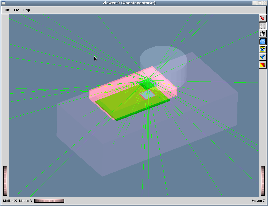
Appliances and Test Structures
In addition to the pixel detectors and associated volumes, AllPix provide methods to place other passive structures in the Simulation volume (ie, support structure, source casing etc...). The additional volume can be of two categories :- Test Structures : Test Structure are fixed volume in the simulation volume, they move independently of the Pixel Detectors (ex : Shielding, source casing, support structures)
- Appliances : Appliances are bound to a Pixel Detector instance ie: Rotation and Translation of the Pixel Detector will also be propagated to the appliance (ex: Detector shielding, cabling, scintillators etc ..)
- Timepix Detector with Lead brick (gray) and Am241 source holder( Cylinder) (test Structure) and Chip Board protector attached to Timepix PCB (Red, Appliance)
Writing a Macro to drive your simulation
The typical structure of an AllPix simulation script is as follow :- Geometry description (AllPix specific commands) : Placing the detectors, test structures, scintillators and appliances
- Physics List declaration (AllPix specific commands) : Selection of the physics list to be used (ex: emstandard_opt0, LIVERMORE_FTFP_BERT)
- Initialization : Initialization of GEANT4 (/run/initialize) and AllPix framework (/aalpix/det/update)
- Verbose Controls
- Visualization Controls
- Telescope specific output Controls
- Beam Definition and Simulation scenario Controls
Generate a macro from the alignment files of the test beams
In the share folder, the script "WriteMacro.py" generates a macro by reading alignment values found by the test beam data and also the gear files used for the test beam analysis. This script uses the file "GeneralMacro.in" which contains a general structure for the macro file and sets the values for the position of the telescope planes. Use the following commands to run the script:cd share source setup_pyLCIO.sh python WriteMacro.py MacroName OutFolder preAlign Align DUTAlign GearFile Energy FrameNbwhere MacroName is the name given to the ouput macro, OutFolder is the folder where the AllPix outputs are saved, preAling and Align are the .slcio files obtained once the telescope is aligned (using EUTelescope analysis framework) and DUTAlign is the file containing the alignment for the DUT (the file should be in the form of: alpha beta gamma x y), GearFile is the xml file which contains the information about the position of the telescope planes and the DUT, Energy is the beam energy and FrameNb corresponds to the number of events.
Geometry Description
Sensor positioning
The sensor that were described in last section can be placed in the simulation geometry using the following command :/allpix/det/setId 300 /allpix/det/setPosition -0.0 -0.0 0.0 mm /allpix/det/setRotation -0.0 180.0 180.0 deg/allpix/det/setId refer to the id number associated to each detector described in the pixeldetector.xml file. /allpix/det/setPosition and /allpix/det/setRotation describe respectively the rotation and position of the sensitive detector in the global geometry of the simulation.
Test structures and appliances
Test structures can be placed in the global geometry with the following self explanatory commands :/allpix/extras/setTestStructureType 8 /allpix/extras/setTestStructurePosition -0.492158130371 -0.17583204793 305.0 mm /allpix/extras/setTestStructureRotation -0.0 -0.0 0.0032635 deg /allpix/extras/setTestStructureDetLink 302/allpix/extras/setTestStructureDetLink 302 is used to make sure that the volume occupied by the sensor 302 do not overlap with the test structure. The volume of detector with ID 302 is substracted from the test structure volume To place an appliance (in the local coordinate of the sensors they associate), use the following commands :
/allpix/extras/setApplianceType 1
/allpix/extras/setAppliancePosition  0. 0. 0. mm
/allpix/extras/setWrapperEnhancement  0.0  0.0 50 mm
setApplianceType is used to select which appliance to use. SetWrapperEnhancement extend the wrapper volume around the detector to insure that it fully contains the appliance. The order the appliances are declared in the simulation macro will define the sensor to which they are associated, following the sensor declaration order.
Scintillator placement
If your simulation make use of the EUDET Telescope (with EUTELESCOPE environnement variable defined at compilation time), you will need to position the scintillator tiles used to trigger the telescope. If all scintillator tiles define detect the passage of a particle, the telescope data are recorded. You can place the scintillator with the following command :/allpix/eudet/scint1Pos 0.0 0.0 -24.0 mm # offset of 18mm +/- 6mm with of scinti /allpix/eudet/scint2Pos 0.0 0.0 -18.0 mm /allpix/eudet/scint3Pos 0.0 0.0 690.8 mm /allpix/eudet/scint4Pos 0.0 0.0 696.8 mmScintillator default dimensions are 22x10.8x6mm.
AllPix specific Macro commands
You can select your favorite physics list from the simulation macro using the following commands:/allpix/phys/Physics LIVERMORE_FTFP_BERTThe available physics list are : emstandard_opt0, emstandard_opt1,emstandard_opt2,emstandard_opt3,FTFP_BERT_EMV, FTFP_BERT_EMY, FTFP_BERT_EMX,FTFP_BERT, FTF_BIC, LHEP,QBBC, QGSC_BERT, QGSP, QGSP_BERT, QGSP_FTFP_BERT, QGSP_BERT_EMV, QGSP_BERT_EMX, QGSP_BERT_HP, QGSP_BIC, QGSP_BIC_EMY, QGS_BIC, QGSP_BIC_HP, LIVERMORE_FTFP_BERT.
Initialization
/run/initialize
/allpix/det/update
This command is called to initialize the geometry and the physics models to be used during your simulation. All sensor, test structures and appliances must be defined before calling that statement. Physics list to be used and physics cuts to be applied must be defined before initializing the simulation framework with this command.
Verbosity Controls
The verbose of the different aspect of the simulation can be modified with the following statements :/run/verbose 0 /control/verbose 0 /control/saveHistory /tracking/verbose 0 /allpix/phys/verbose 0Verbosity level 0 is the most silent, and increasing this value will add more verbosity to the allpix output.
Vizualisation Controls
The following describe a typical statement for activating visualization in allpix. Uncomment one of the /vis/open statement to activate visualization. For more info on these commands, please refer to the GEANT4 documentation.#################################################################### # Visualization /vis/scene/create #/vis/scene/add/axes 0. 0. 0. 10. cm /vis/scene/add/volume World -1 2 /vis/viewer/set/style s #/vis/open OIX 1024x768-100+100 #/vis/open OGLIXm 1024x768-100+100 #/vis/open RayTracer #/vis/open OGLIQt #/vis/open OGLSQt #/vis/open OIX #/vis/open OGLIX 1024x768-100+100 #/vis/open OGLSXm #/vis/open DAWNFILE #/vis/open OGLSX #/vis/open OGL 600x600-0+0 /vis/viewer/set/background 0.4 0.5 0.6 /vis/viewer/set/viewpointThetaPhi 20 50 /vis/viewer/zoom 2.0 /vis/viewer/flush #################################################################### # Draw trajectories at end of event, showing trajectory points as # markers of size 2 pixels #/vis/scene/add/trajectories #/vis/modeling/trajectories/create/drawByCharge #/vis/modeling/trajectories/drawByCharge-0/default/setDrawStepPts false #/vis/modeling/trajectories/drawByCharge-0/default/setStepPtsSize 2 #/vis/scene/endOfEventAction accumulate
Telescope Output Controls
To generate ASCII files that can be used in the EUTELESCOPE framework, use the following set of controls:#################################################################### # Write Telescope files /allpix/timepixtelescope/setFolderPath /VertexScratch/workspace/mbenoit/test/Run000008 /allpix/timepixtelescope/setEventIDcolumn 0 /allpix/timepixtelescope/setSumTOT 1 /allpix/timepixtelescope/write 1This will create on ASCII file per frame in the specified folder, which contains all the digitised hits for each simulated sensor planes.
Simple ROOT file Output Controls
To generate simple ROOT file containing a tree with the simulated data, a set of commands are available , as shown in this example :#################################################################### # Write ROOT File /allpix/WriteROOTFiles/write 1 /allpix/WriteROOTFiles/setFolderPath /myDataFolder/FEI4Alone/run2The first command toggle the writing of the files by allpix (one per sensor). The second line specifiy the folder where the files are to be written, An example of how to read and cluster the tree produced by the command using pyROOT can be found in share/SimpleClusteredAllpixRootFile.py
LCIO file Output for EUTelescope Controls
To generate a LCIO file containing the simulated data, a set of commands are available , as shown in this example :#################################################################### # Write LCIO File /allpix/eutelescope/write 1 /allpix/eutelescope/setFolderPath /myDataFolder/FEI4Alone/run2 /allpix/eutelescope/WriteEventID 0The first command toggle the writing of the files by allpix (one per sensor). The second line specify the folder where the files are to be written, The third line toggles the writing of a fourth field for each sensor in the slcio file. This is needed for compatibility with certain setups. Allpix must be compiled with LCIO support for this to work. Mimosa26 data are written as zsdata_m26 collection while the other DUT are written as collection such as Det401, where 401 is the allpix detector Id.
Beam Definition and Simulation scenario Controls
#########################
# gammas
#/gps/source/intensity 75.17
/gps/particle gamma
/gps/pos/type Plane
/gps/pos/shape Circle
/gps/pos/centre 0 0 22 mm
/gps/pos/radius 2.5 mm
/gps/direction  0 0 -1
/gps/ene/type User
/gps/hist/type energy
# spectra
#/gps/hist/point  0.0139  37
#/gps/hist/point  0.026345  2.27
/gps/hist/point  0.059541  59.541
/gps/ang/type iso
/gps/mintheta 0
/gps/maxtheta 1.8

####################################################################
# Shoot
/allpix/beam/frames 1
/allpix/beam/type const 50
/allpix/beam/on
Analysis of your Simulation results
Analysis in the Mafalda Framework
Analysis in the EUTELESCOPE Framework
In order to input your simulated data in EUTELESCOPE, you will need to convert the generated ASCII files into the LCIO format. For this, use the TelescopeConverter.py python script located in the "share" folder. The python script takes a tarball as input, so first run the following command to tar all your ASCII files:tar -czvf <tarball-filename>.tar.gz <path-to-the-folder-containing-the-mpx-ascii-files>You can now perform the conversion to the LCIO format:
python TelescopeConverter.py <input-tarball> <output-file-name>.slcio <list-of-DUT-sensorID>For example, if you have simulated run number 999 with the telescope as well as your favourite three DUTs with sensor ID 410, 412, and 543, the commands will look like this:
tar -czvf run000999.tar.gz ./run000999/*
python TelescopeConverter.py run000999.tar.gz run000999.slcio 410 412 543
You now have a .slcio file, which has the exact same format as the one created in EUTELESCOPE by the converter when you have testbeam data. You can inspect the contents by running the following command:
dumpevent run000999.slcio <event-number>-- MathieuB - 12 Feb 2014


| I | Attachment | History | Action | Size | Date | Who | Comment |
|---|---|---|---|---|---|---|---|
| |
Example_TestStruct_Appliance.png | r1 | manage | 44.5 K | 2014-02-17 - 13:37 | MathieuB | |
| |
G4OpenGL_030.jpg | r1 | manage | 94.6 K | 2012-10-20 - 01:14 | JohnIdarraga | allpix simulation of Timepix stack |
| |
Vis_example.txt | r1 | manage | 3.6 K | 2014-02-17 - 10:57 | MathieuB | |
| |
pixelExample.png | r1 | manage | 20.8 K | 2014-02-17 - 10:42 | MathieuB | Pixel Geometry example, 2x2 pixels with Chip and Bump shift |
| |
pixelExample_bumps.png | r1 | manage | 22.2 K | 2014-02-17 - 10:42 | MathieuB | Pixel Geometry example, 2x2 pixels with Chip and Bump shift, zoom on bumps |
Webs
- ABATBEA
- ACPP
- ADCgroup
- AEGIS
- AfricaMap
- AgileInfrastructure
- ALICE
- AliceEbyE
- AliceSPD
- AliceSSD
- AliceTOF
- AliFemto
- ALPHA
- Altair
- ArdaGrid
- ASACUSA
- AthenaFCalTBAna
- Atlas
- AtlasLBNL
- AXIALPET
- CAE
- CALICE
- CDS
- CENF
- CERNSearch
- CLIC
- Cloud
- CloudServices
- CMS
- Controls
- CTA
- CvmFS
- DB
- DefaultWeb
- DESgroup
- DPHEP
- DM-LHC
- DSSGroup
- EGEE
- EgeePtf
- ELFms
- EMI
- ETICS
- FIOgroup
- FlukaTeam
- Frontier
- Gaudi
- GeneratorServices
- GuidesInfo
- HardwareLabs
- HCC
- HEPIX
- ILCBDSColl
- ILCTPC
- IMWG
- Inspire
- IPv6
- IT
- ItCommTeam
- ITCoord
- ITdeptTechForum
- ITDRP
- ITGT
- ITSDC
- LAr
- LCG
- LCGAAWorkbook
- Leade
- LHCAccess
- LHCAtHome
- LHCb
- LHCgas
- LHCONE
- LHCOPN
- LinuxSupport
- Main
- Medipix
- Messaging
- MPGD
- NA49
- NA61
- NA62
- NTOF
- Openlab
- PDBService
- Persistency
- PESgroup
- Plugins
- PSAccess
- PSBUpgrade
- R2Eproject
- RCTF
- RD42
- RFCond12
- RFLowLevel
- ROXIE
- Sandbox
- SocialActivities
- SPI
- SRMDev
- SSM
- Student
- SuperComputing
- Support
- SwfCatalogue
- TMVA
- TOTEM
- TWiki
- UNOSAT
- Virtualization
- VOBox
- WITCH
- XTCA
Welcome Guest Login or Register
 |
|
or Ideas, requests, problems regarding TWiki? use Discourse or Send feedback